explain with the help of a labeled ray diagram,the defect of vision called hypermetropia,and how is it connected by lens?

Ray Diagrams

The line of sight principle suggests that in order to view an image of an object in a mirror, a person must sight along a line at the image of the object. When sighting along such a line, light from the object reflects off the mirror according to the law of reflection and travels to the person's eye. This process was discussed and explained earlier in this lesson. One useful tool that is frequently used to depict this idea is known as a ray diagram. A ray diagram is a diagram that traces the path that light takes in order for a person to view a point on the image of an object. On the diagram, rays (lines with arrows) are drawn for the incident ray and the reflected ray. Complex objects such as people are often represented by stick figures or arrows. In such cases it is customary to draw rays for the extreme positions of such objects.

This section of Lesson 2 details and illustrates the procedure for drawing ray diagrams. Let's begin with the task of drawing a ray diagram to show how Suzie will be able to see the image of the green object arrow in the diagram below. For simplicity sake, we will suppose that Suzie is viewing the image with her left eye closed. Thus, we will focus on how light travels from the two extremities of the object arrow (the left and right side) to the mirror and finally to Suzie's right eye as she sights at the image. The four steps of the process for drawing a ray diagram are listed, described and illustrated below.

1. Draw the image of the object.

Use the principle that the object distance is equal to the image distance to determine the exact location of the object. Pick one extreme on the object and carefully measure the distance from thisextreme point to the mirror. Mark off the same distance on the opposite side of the mirror and mark the image of this extreme point. Repeat this process for all extremes on the object until you have determined the complete location and shape of the image. Note that all distance measurements should be made by measuring along a segment that is perpendicular to the mirror.


2. Pick one extreme on the image of the object and draw the reflected ray that will travel to the eye as it sights at this point.

Use the line of sight principle: the eye must sight along a line at the image of the object in order to see the image of the object. It is customary to draw a bold line for the reflected ray (from the mirror to the eye) and a dashed line as an extension of this reflected ray; the dashed line extends behind the mirror to the location of the image point. The reflected ray should have an arrowhead upon it to indicate the direction that the light is traveling. The arrowhead should be pointing towards the eye since the light is traveling from the mirror to the eye, thus enabling the eye to see the image.


3. Draw the incident ray for light traveling from the corresponding extreme on the object to the mirror.

The incident ray reflects at the mirror's surface according to the law of reflection. But rather than measuring angles, you can merely draw the incident ray from the extreme of the object to the point of incidence on the mirror's surface. Since you drew the reflected ray in step 2, the point of incidence has already been determined; the point of incidence is merely the point where the line of sight intersects the mirror's surface. Thus draw the incident ray from the extreme point to the point of incidence. Once more, be sure to draw an arrowhead upon the ray to indicate its direction of travel. The arrowhead should be pointing towards the mirror since light travels from the object to the mirror.


4. Repeat steps 2 and 3 for all other extremities on the object.

After completing steps 2 and 3, you have only shown how light travels from a single extreme on the object to the mirror and finally to the eye. You will also have to show how light travels from the other extremes on the object to the eye. This is merely a matter of repeating steps 2 and 3 for each individual extreme. Once repeated for each extreme, your ray diagram is complete.


The best way to learn to draw ray diagrams involves trying it yourself. It's easy. Merely duplicate the two setups below onto a blank sheet of paper, grab a ruler/straightedge, and begin. If necessary, refer to the four-step procedure listed above. When finished, compare your diagram with the completed diagrams at the bottom of this page.


Uses of Ray Diagrams

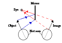
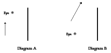
Ray diagrams can be particularly useful for determining and explaining why only a portion of the image of an object can be seen from a given location. The ray diagram at the right shows the lines of sight used by the eye in order to see a portion of the image in the mirror. Since the mirror is not long enough, the eye can only view the topmost portion of the image. The lowest point on the image that the eye can see is that point in line with the line of sight that intersects the very bottom of the mirror. As the eye tries to view even lower points on the image, there is not sufficient mirror present to reflect light from the lower points on the object to the eye. The portion of the object that cannot be seen in the mirror is shaded green in the diagram below.

Similarly, ray diagrams are useful tools for determining and explaining what objects might be viewed when sighting into a mirror from a given location. For example, suppose that six students - Al, Bo, Cy, Di, Ed, and Fred sit in front ofa plane mirror and attempt to see each other in the mirror. And suppose the exercise involves answering the following questions: Whom can Al see? Whom can Bo see? Whom can Cy see? Whom can Di see? Whom can Ed see? And whom can Fred see?

The task begins by locating the images of the given students. Then, Al is isolated from the rest of the students and lines of sight are drawn to see who Al can see. The leftward-most student whom Al can see is the student whose image is to the right of the line of sight that intersects the left edge of the mirror. This would be Ed. The rightward-most student who Al can see is the student whose image is to the left of the line of sight that intersects the right edge of the mirror. This would be Fred. Al could see any student positioned between Ed and Fred by looking at any other positions along the mirror. However in this case, there are no other students between Ed and Fred; thus, Ed and Fred are the only students whom Al can see? The diagram below illustrates this using lines of sight for Al.
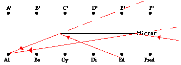
 

Of course the same process can be repeated for the other students by observing their lines of sight. Perhaps you will want to try to determine whom Bo, Cy, Di, Ed, and Fred can see? Then check your answers by clicking the button below.


Check Your Understanding

1. Six students are arranged in front of a mirror. Their positions are shown below. The image of each student is also drawn on the diagram. Make the appropriate line of sight constructions to determine that students each individual student can see.
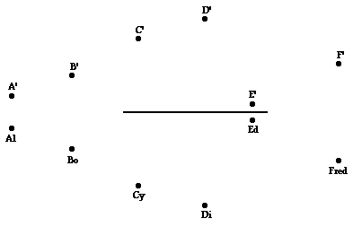


Here are completed diagrams for the two examples given above.
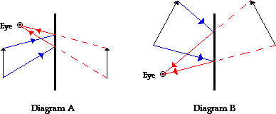
Back to Diagram.


  • 0

Converging Lenses - Ray Diagrams

One theme of the Reflection and Refraction units of The Physics Classroom Tutorial has been that we see an object because light from the object travels to our eyes as we sight along a line at the object. Similarly, we see an image of an object because light from the object reflects off a mirror or refracts through a transparent material and travel to our eyes as we sight at the image location of the object. From these two basic premises, we have defined the image location as the location in space where light appears to diverge from. Because light emanating from the object converges or appears to diverge from this location, a replica or likeness of the object is created at this location. For both reflection and refraction scenarios, ray diagrams have been a valuable tool for determining the path of light from the object to our eyes.

In this section of Lesson 5, we will investigate the method for drawing ray diagrams for objects placed at various locations in front of adouble convex lens. To draw these ray diagrams, we will have to recall the three rules of refraction for a double convex lens:

  • Any incident ray traveling parallel to the principal axis of a converging lens will refract through the lens and travel through the focal point on the opposite side of the lens.
  • Any incident ray traveling through the focal point on the way to the lens will refract through the lens and travel parallel to the principal axis.
  • An incident ray that passes through the center of the lens will in effect continue in the same direction that it had when it entered the lens.

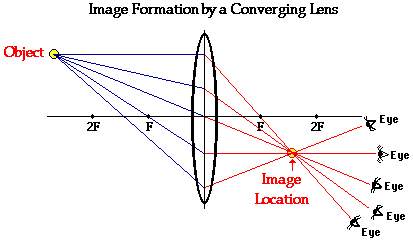
Earlier in this lesson, the following diagram illustrating the path of light from an object through a lens to an eye placed at various locations was shown.

In this diagram, five incident rays are drawn along with their corresponding refracted rays. Each ray intersects at the image location and then travels to the eye of an observer. Every observer would observe the same image location and every light ray would follow the Snell's Law of refraction. Yet only two of these rays would be needed to determine the image location since it only requires two rays to find the intersection point. Of the five incident rays drawn, three of them correspond to the incident rays described by our three rules of refraction for converging lenses. We will use these three rays through the remainder of this lesson, merely because they are the easiest rays to draw. Certainly two rays would be all that is necessary; yet the third ray will provide a check of the accuracy of our process.


Step-by-Step Method for Drawing Ray Diagrams

The method of drawing ray diagrams for double convex lens is described below. The description is applied to the task of drawing a ray diagram for an object located beyond the 2F point of a double convex lens.

1. Pick a point on the top of the object and draw three incident rays traveling towards the lens.
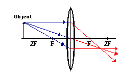
Using a straight edge, accurately draw one ray so that it passes exactly through the focal point on the way to the lens. Draw the second ray such that it travels exactly parallel to the principal axis. Draw the third incident ray such that it travels directly to the exact center of the lens. Place arrowheads upon the rays to indicate their direction of travel.


2. Once these incident rays strike the lens, refract them according to the three rules of refractionfor converging lenses.

The ray that passes through the focal point on the way to the lens will refract and travel parallel to the principal axis. Use a straight edge to accurately draw its path. The ray that traveled parallel to the principal axis on the way to the lens will refract and travel through the focal point. And the ray that traveled to the exact center of the lens will continue in the same direction. Place arrowheads upon the rays to indicate their direction of travel. Extend the rays past their point of intersection.


3. Mark the image of the top of the object.

The image point of the top of the object is the point where the three refracted rays intersect. All three rays should intersect at exactly the same point. This point is merely the point where all light from the top of the object would intersect upon refracting through the lens. Of course, the rest of the object has an image as well and it can be found by applying the same three steps to another chosen point. (See note below.)


4. Repeat the process for the bottom of the object.
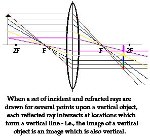
One goal of a ray diagram is to determine the location, size, orientation, and type of image that is formed by the double convex lens. Typically, this requires determining where the image of the upper and lower extreme of the object is located and then tracing the entire image. After completing the first three steps, only the image location of the top extreme of the object has been found. Thus, the process must be repeated for the point on the bottom of the object. If the bottom of the object lies upon the principal axis (as it does in this example), then the image of this point will also lie upon the principal axis and be the same distance from the mirror as the image of the top of the object. At this point the entire image can be filled in.


Some students have difficulty understanding how the entire image of an object can be deduced once a single point on the image has been determined. If the object is merely a vertical object (such as the arrow object used in the example below), then the process is easy. The image is merely a vertical line. In theory, it would be necessary to pick each point on the object and draw a separate ray diagram to determine the location of the image of that point. That would require a lot of ray diagrams as illustrated in the diagram below.

Fortunately, a shortcut exists. If the object is a vertical line, then the image is also a vertical line. For our purposes, we will only deal with the simpler situations in which the object is a vertical line that has its bottom located upon the principal axis. For such simplified situations, the image is a vertical line with the lower extremity located upon the principal axis.

The ray diagram above illustrates that when the object is located at a position beyond the 2F point, the image will be located at a position between the 2F point and the focal point on the opposite side of the lens. Furthermore, the image will be inverted, reduced in size (smaller than the object), and real. This is the type of information that we wish to obtain from a ray diagram. These characteristics of the image will be discussed in more detail in the next section of Lesson 5.

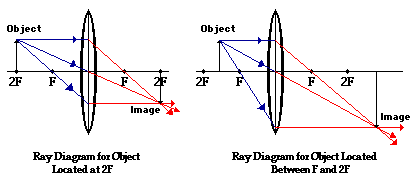
Once the method of drawing ray diagrams is practiced a couple of times, it becomes as natural as breathing. Each diagram yields specific information about the image. The two diagrams below show how to determine image location, size, orientation and type for situations in which the object is located at the 2F point and when the object is located between the 2F point and the focal point.

It should be noted that the process of constructing a ray diagram is the same regardless of where the object is located. While the result of the ray diagram (image location, size, orientation, and type) is different, the same three rays are always drawn. The three rules of refraction are applied in order to determine the location where all refracted rays appear to diverge from (which for real images, is also the location where the refracted rays intersect).


Ray Diagram for Object Located in Front of the Focal Point

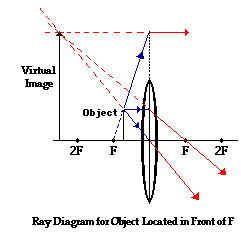
In the three cases described above - the case of the object being located beyond 2F, the case of the object being located at 2F, and the case of the object being located between 2F and F - light rays are converging to a point after refracting through the lens. In such cases, areal image is formed. As discussed previously, a real image is formed whenever refracted light passes through the image location. While diverging lenses always produce virtual images, converging lenses are capable of producing both real and virtual images. As shown above, real images are produced when the object is located a distance greater than one focal length from the lens. A virtual image is formed if the object is located less than one focal length from the converging lens. To see why this is so, a ray diagram can be used.

A ray diagram for the case in which the object is located in front of the focal point is shown in the diagram at the right. Observe that in this case the light rays diverge after refracting through the lens. When refracted rays diverge, a virtual image is formed. The image location can be found by tracing all light rays backwards until they intersect. For every observer, the refracted rays would seem to be diverging from this point; thus, the point of intersection of the extended refracted rays is the image point. Since light does not actually pass through this point, the image is referred to as a virtual image. Observe that when the object in located in front of the focal point of the converging lens, its image is an upright and enlarged image that is located on the object's side of the lens. In fact, one generalization that can be made about all virtual images produced by lenses (both converging and diverging) is that they are always upright and always located on the object's side of the lens.


Ray Diagram for Object Located at the Focal Point

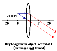
Thus far we have seen via ray diagrams that a real image is produced when an object is located more than one focal length from a converging lens; and a virtual image is formed when an object is located less than one focal length from a converging lens (i.e., in front of F). But what happens when the object is located at F? That is, what type of image is formed when the object is located exactly one focal length from a converging lens? Of course a ray diagram is always one tool to help find the answer to such a question. However, when a ray diagram is used for this case, an immediate difficulty is encountered. The diagram below shows two incident rays and their corresponding refracted rays.

For the case of the object located at the focal point (F), the light rays neither converge nor diverge after refracting through the lens. As shown in the diagram above, the refracted rays are traveling parallel to each other. Subsequently, the light rays will not converge to form a real image; nor can they be extended backwards on the opposite side of the lens to intersect to form a virtual image. So how should the results of the ray diagram be interpreted? The answer: there is no image!! Surprisingly, when the object is located at the focal point, there is no location in space at which an observer can sight from which all the refracted rays appear to be coming. An image cannot be found when the object is located at the focal point of a converging lens.


  • 2


Ray Diagrams for Lenses

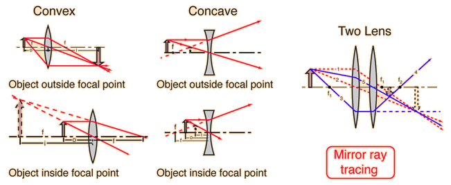
The image formed by a single lens can be located and sized with three principal rays. Examples are given for converging and diverging lenses and for the cases where the object is inside and outside the principal focal length.

The "three principal rays" which are used for visualizing the image location and size are:

  1. A ray from the top of the object proceeding parallel to the centerline perpendicular to the lens. Beyond the lens, it will pass through the principal focal point. For a negative lens, it will proceed from the lens as if it emanated from the focal point on the near side of the lens.
  2. A ray through the center of the lens, which will be undeflected. (Actually, it will be jogged downward on the near side of the lens and back up on the exit side of the lens, but the resulting slight offset is neglected for thin lenses.)
  3. A ray through the principal focal point on the near side of the lens. It will proceed parallel to the centerline upon exit from the lens. The third ray is not really needed, since the first two locate the image.
  • -2


Optional Unit VI: Optics
B. Lenses


Key Concepts

Lenses have curved surfaces, or a very large number of flat surfaces located at slightly different angles. (i.e., Fresnel lens)


Converging lenses (positive lenses) are thicker at the centre than at the edges.


Diverging lenses (negative lenses) are thicker at the edges than at the centre.


(Only thin, single lenses are dealt with in Physics 20. Note as well that the terms concave and convex, as applied to lenses, can be misleading. A meniscus lens has both a concave and a convex surface, but the thickness at the centre compared with the edges determines if it behaves as a converging or a diverging lens.)

The optical centre of the lens is located at its geometric centre.


The principal axis is a construction line drawn perpendicular to the lens, through the optical centre.


Rays parallel to the principal axis will converge when passing through a converging lens, and diverge when passing through a diverging lens.


The principal focus (F) is a point on the principal axis where light comes to a focus (for a converging lens) or appears to be diverging from (for a diverging lens). Two foci exist, equidistant on either side of the lens, since light behaves the same way when travelling in either direction (Principle of Reversibility). The two foci, F and F' are called the primary principal focus and the secondary principal focus, respectively. F, sometimes also referred to as the primary focal point, is shown on the right side of a converging lens, and on the left side of a diverging lens, while F', the secondary focal point is shown on the opposite side of each respective lens.)

Ray diagrams are used to show rays passing through a lens.


Ray diagrams can be useful in determining the characteristics of an image formed by a lens.

By convention, incident rays are shown travelling from left to right on ray diagrams. A dotted line is usually drawn through the lens at the optical centre, perpendicular to the principal axis.


Ray diagrams should always be drawn and labelled neatly, accurately, and to some appropriate scale.


The focal length is the distance between the principal focus and the optical centre of the lens.

The focal plane is an imaginary plane perpendicular to the principal axis at the focal point. Parallel rays will converge through a converging lens somewhere on the focal plane.

Incident light rays are refracted twice by a lens; once at each boundary. Partial reflection may also occur. (In optical systems, partial reflection is undesirable. It can be minimized by using optical lens coatings. Coated lenses provide superior image quality.)


To simplify matters on ray diagrams, incident rays can be shown to refract at the construction line passing through the optical centre of the lens. For a thin lens this leads to a reasonably close approximation because the lateral displacement is quite small.


Light rays that have travelled over a large distance are effectively parallel.


Lenses can form either real or virtual images.


The rules for drawing ray diagrams for converging and diverging lenses can be used to determine the characteristics of an image formed by a lens.


Lens equations can be used to determine the characteristics of an image. (Refer to page 111 for lens equations and sign conventions.)


A diverging lens always forms an erect, virtual image which is diminished in size. It is located closer to the lens than the object, between the principal focal point and the lens.


To correct for spherical aberration in lenses, achromatic lenses can be used. (Spherical aberration in lenses can be corrected by using aspheric lenses, or by using thin lens combinations which cancel out aberrations. Achromatic lenses, designed to correct for chromatic aberration at some wavelengths, can also help to reduce spherical aberration.)

Lens defects are called aberrations. They hinder the quality of the image formed in an optical system.

Lenses are used in many different kinds of practical applications. (Several should be studied.)


An optical system may use a combination of mirrors, lenses, prisms, and other kinds of optical devices.

An image formed by one component in an optical system can serve as an object for a different component.


The image characteristics formed by converging lenses depend on the location of the object. This table summarizes the characteristics of images found in a converging mirror based onthe location of the object.


Image Characteristics

Object locationMagnificationAttitudeTypePosition
near infinity< -1invertedrealat F
beyond 2F< -1invertedrealbetween F & 2F
at 2F-1invertedrealat 2F
between 2F and F> -1invertedrealbeyond 2F
between F and O> +1erectvirtualsame side as object
at Fundefined   

(These characteristics should be developed experimentally, and verified with the use of ray diagrams and equations. Rote memorization should be discouraged and avoided.)


Rules for Drawing Ray Diagrams for Converging and Diverging Lenses

(Parenthetical remarks refer specifically to diverging lenses)


  1. An incident ray that is parallel to the principal axis is refracted such that it passes through (or appears to have originated from) the principal focus (F).


  2. An incident ray passing through (or heading toward) the secondary principal focus (F') is refracted such that it travels parallel to the principal axis.


  3. An incident ray passing through the optical centre of the lens continues to travel in a straight line.


Learning Outcomes

Students will increase their abilities to:


  1. Define the following terms: converging (positive) lens, diverging (negative) lens, optical centre, principal axis, principal focus, focal length, focal plane, achromatic lens, virtual object.


  2. Distinguish between a converging (positive) lens and a diverging (negative) lens.


  3. Draw diagrams of converging and diverging lenses, showing the principal axis and important points on the principal axis for each type of lens.


  4. Draw neat, properly labelled, accurate, scaled ray diagrams for single thin lenses.


  5. Apply the rules for drawing ray diagrams for converging and diverging lenses (parallel-ray method) to draw an object on the principal axis and locate the position and other characteristics of its image.


  6. Use a ray diagram to interpret the characteristics of an image formed by a lens.


  7. Demonstrate an understanding of the importance and use of a procedure of verification.


  8. Recognize that, even though light rays are refracted at both surfaces by a lens, for thin lenses the incident rays can be shown refracting at the construction line passing through the optical centre of the lens.


  9. Explain why light rays travelling over a long distance are effectively parallel when they reach a lens (or other type of optical system).


  10. Apply lens equations, in conjunction with ray diagrams and other methods, to solve problems in optics dealing with lenses.


  11. Explain one method that can be used to correct for spherical aberration in lenses.


  12. Distinguish between a real object and a virtual object.


  13. Identify various useful applications of lenses, and show their importance to society.

Images formed by a converging lens
  Characteristics of the Image
a) Distant objectRay diagram for distant objectReal
Inverted
Smaller than object
At F
b) Object at 2FRay diagram for object at 2FReal
Inverted
Same size
At 2F
c) Object between 2F ans FRay diagram for object between 2F and FReal
Inverted
Larger than object
Beyond 2F
d) Object at FRay diagram for object at FNo image
Refracted rays
are parallel
e) Object between F and lensRay diagram for object between F and lensVirtual
Erect
Larger than object
Behind the object on the same side of the lens
Image formed by a diverging lens
e) Object at FRay diagram for diverging lensCharacteristics of the image regardless of object postion
Virtual
Erect
Smaller than object
Between object and lens

Teaching Suggestions, Activities and Demonstrations


  1. Perform an activity to investigate image formation in converging and diverging lenses.


  2. Place a light source, a converging lens, and a screen on a stand. Determine the image position at various different distances between the object and the lens. Find the focal length and the lens power. Determine the magnification for specific object positions. Repeat with several different positive lenses. Draw ray diagrams illustrating each specific case. State the image characteristics for all of the possible cases. For an added challenge, repeat using two different lenses placed together.


  3. Place a converging and a diverging lens on an optical bench. Look through the lens combination from both directions at distant objects. Adjust the separation of the lenses.


  4. The arrangement described in #3 above was used to develop the first optical telescopes. Background historical information on the development of the telescope could be researched independently by students.


  5. Compare Galilean and Keplerian telescopes in terms of image characteristics. Using ray diagrams and data collected through experimentation, show how the image is formed in each of the telescopes.


  6. Various ray box demonstrations and activities are useful to incorporate into this section.


  7. Use computers as analytical tools to solve problems, perform simulations, and explore new environments in micro worlds.


  8. A useful model which simulates the refraction of sunlight through the atmosphere involves preparing a solution in a beaker which contains about 900 mL of water, 5 g of sodium thiosulphate and 5 mL of concentrated hydrochloric acid. (Always add the acid to water. Never add water to the acid. The solution is fairly safe when diluted, but the concentrated acid is very corrosive.)

    A colloidal solution of sulphur forms. Shine a spotlight through the container. Scattered blue light will be evident at right angles to the beam. Use a white screen to examine different regions of the beam. The colours will appear white, yellow, and red. Regions that are blackened completely may also be evident.

    This demonstration is useful for explaining sunsets and the Tyndall Effect. (Save the solution. Pour it into a round-bottomed Florence flask to simulate refraction in lenses.)

  • 0

hypermetropia or far sightedness is a defect of vision in which objects at far distances can be seen clearly but objects at near distances cannot be seen distinctly.
the near point of the eye is farther away than 25 cm. the image is formed behind the retina instead of on the retina itself.
using a convex lens helps in correcting this defect as it corrects the path of the light rays, making it focus on the retina.

  • 1
hypermetropia
 
  • 2
We cannot see nearby objects clearly. It can be corrected by convex lens of correct number.
  • -1
hypermetropia
  • 0
hypermetropia
  • 2
Converging Lenses - Ray Diagrams One theme of the Reflection and Refraction units of The Physics Classroom Tutorial has been that we see an object because light from the object travels to our eyes as we sight along a line at the object. Similarly, we see an image of an object because light from the object reflects off a mirror or refracts through a transparent material and travel to our eyes as we sight at the image location of the object. From these two basic premises, we have defined the image location as the location in space where light appears to diverge from. Because light emanating from the object converges or appears to diverge from this location, a replica or likeness of the object is created at this location. For both reflection and refraction scenarios, ray diagrams have been a valuable tool for determining the path of light from the object to our eyes. In this section of Lesson 5, we will investigate the method for drawing ray diagrams for objects placed at various locations in front of adouble convex lens. To draw these ray diagrams, we will have to recall the three rules of refraction for a double convex lens: Any incident ray traveling parallel to the principal axis of a converging lens will refract through the lens and travel through the focal point on the opposite side of the lens. Any incident ray traveling through the focal point on the way to the lens will refract through the lens and travel parallel to the principal axis. An incident ray that passes through the center of the lens will in effect continue in the same direction that it had when it entered the lens. Earlier in this lesson, the following diagram illustrating the path of light from an object through a lens to an eye placed at various locations was shown. In this diagram, five incident rays are drawn along with their corresponding refracted rays. Each ray intersects at the image location and then travels to the eye of an observer. Every observer would observe the same image location and every light ray would follow the Snell's Law of refraction. Yet only two of these rays would be needed to determine the image location since it only requires two rays to find the intersection point. Of the five incident rays drawn, three of them correspond to the incident rays described by our three rules of refraction for converging lenses. We will use these three rays through the remainder of this lesson, merely because they are the easiest rays to draw. Certainly two rays would be all that is necessary; yet the third ray will provide a check of the accuracy of our process.
  • 1
What are you looking for?